|
these appear on the surface broaches or external broaches which cuts with
shear action, requiring maximum contact with component.
Setting of Broaches-
For most of the conventional operations it is possible to carry out the
job with some change in
tooling and standard clamping etc. However this is not feasible with
broaching since the only
variable is broaching speed and therefore all the other factors must be
corrected during first use
only, which helps in avoiding expensive failure.
It is very important that broaching operation be entrusted to an engineer
or Supervisor who has
longer experience in using broaches, understanding the correct settings
and maintaining the
correctly sharpened broaches. However for a newcomer following steps will
definitely help in
getting improved life.
Internal Broaching-
In the first step it should be ensured that the ram, the faceplate and the
work piece are in exact
alignment. Next it should be ensured that work piece sits on faceplate
exactly perpendicular to
the direction of broach travel. This is particularly important since if
the work piece is not
square, the broached component may not be accurate, the broach may also
drift in bore or
possibly the broach may break. Please refer to fig.2 given below.
In case if the bearing surface of the
work piece is not square with the bore
to be broached then in such cases a
hemispherical bearing can be used to
overcome this problem.
In the next it should be checked that the
puller Clamps the broach properly,
locking securely and releases easily.
Before broaching the ram stops should
be checked to ensure that these are
positioned correctly and these are
securely clamped. Finally, before
broaching is stared it should be ensured
that components fit over the broach
pilot.
Surface broaching-
For surface broaches it should firstly be ensured that alignment of the
ram and the travel of the
ram is relative to the position in the fixture and are in the same plane.
This is normally carried
out using a dial indicator.
When the broaches are fitted in the holder or bolster, great care has to
taken to ensure that
broaches sit properly, there is satisfactory space for removing chips and
there are no burrs or
foreign particles on broaches.
If the broaches are made of several segments then the rise from the last
tooth of each segment
to the first tooth on the following segment should be checked to ensure
that no incorrect or
misfitting broach segment. In some cases segments are manufactured
separately although these
are designed in set, In such cases special care should be taken while
setting so that there is no
mismatch in the profile to be produced.
It should also be ensured that the clamps are working efficiently, the
work piece is correctly
positioned and butting or holding surfaces are clean and free from chips
and burrs. Some times
it is essential that the fixture holding broaches (bolster) is also
checked for clamping and
alignment.
Finally, the ram stops are to be checked to ensure that stroke of the
machine is correct.
General precautions
During the broaching of first component special note should be taken of
the reading of the
pressure gauge or the ammeter. During subsequent broaching careful watch
is to be carried out
to ensure that increase in broaching pressure is not more than 35% of the
initial pressure
reading, which was noted during first use. If abnormal increase in
pressure is observed it
should be considered an indication that broach is worn out.
After producing first component size and the surface finish should be
checked thoroughly and
it be checked occasionally during the whole broaching operation.
Setting of Broaches
In turning, milling and other operations some amount of wear on the tools
can be tolerated but
in broaches the cutting edges must be maintained in a sharp condition.
Cutting with a worn-out
broach may not only damage the cutting teeth but can cause the broach to
drift in the hole and
can destroy the accuracy by broaching in inclined axis. This phenomenon
normally occurs due
to non-homogenous nature of the component material.
When a broach requires sharpening there are always sufficient indications.
These can be poor
be taken out from the machine immediately as further use can not only
deteriorate the
components but it can cause a damage to the broach which can be beyond
repair and keep its
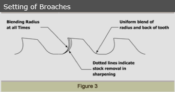
first class condition. Please refer to fig.3
 given below.
You may note that in this
correct form and contour of
the broach are maintained
very carefully, and the radius
is accurately blended to
prevent the interference with
the chip curling.
All the internal and the
surface broaches are
sharpened on the front face
only and only just sufficient
enough material is to
removed to restore the
original sharpness.
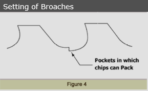
Please refer to fig.4
 Selection of correct Coolant
There are no real secrets or off-the-shelf recommendations for a perfect
coolant. The coolant
that is excellent for broaching high-alloy steel may be very poor for
broaching stainless, and
vice versa. The action of a coolant in reducing friction depends entirely
upon the chemical
properties involved, and the coolant must be tailored and adjusted with
the correct amount and
types of additives. Too weak a
reaction and the lubricating film may not form. Too strong a reaction, and
both the tool and the
work piece may be chemically attacked and worn down.
At low cutting speeds, coolants vary greatly in their ability to reduce
chip-to-tool face friction.
However, at faster cutting speeds, there is less time for coolant to
penetrate, less time to react,
and therefore, less friction-reducing ability. Good cooling and wetting
abilities are much more
important at faster speeds since the time for chemical reactions to form
adsorbed films is
measured in milliseconds.
Thus the main functions of a broaching coolant can be as below:
Dissipate heat generated by the cutting action.
Lubricate the tooth surfaces and chips to facilitate chip flow
Flush the chips from between the teeth
Fortified petroleum coolants are used most often, (these are known neat
cutting oils) but some
of the new heavy duty water soluble coolants have excellent ability to
dissipate heat, are
cleaner to work with, and reduce fire hazards while, in some cases,
allowing broach speed to
be increased. However some have proven to reduce broach life.
If the component material is not varying with the jobs available for
broaching it is advised that
a reputed manufacturer may be contacted for the latest developed coolant.
The supplier is
normally more experienced and proven to suggest the most suitable coolant.
There are very
popular brands developed by leading coolant manufacturer viz. Castrol,
Shell, Tidewater & oil
etc. Who can readily offer the services at their cost.
Reasons of broach breakage
If the broach is designed by experts, manufactured properly and used with
correct care it
should definitely last long. However after grinding many times it becomes
no longer capable
of sustaining the broaching load. If this type breakage takes place it can
only be result of
careless or improper handling. Following are the basic reasons of broach
breakages:
1 Overloading -
In many cases the broach drawings mention the pulling load or the
broaching pressure
in Kgs. or Tones, which should considered for setting of the broaching
machine. In
case if this is not mentioned, the pulling load observed during first
component
broaching should be noted. For Steel components having normal hardness
this load
may be allowed to increase up to 30 to 35% over the first
component-broaching load.
Any further increase in pulling load may cause the overloading of the
broach and can
be prime cause of breakage. Following are some basic reasons for
overloading of the
broach:
a) Permitting excessive wear on the cutting edges. This
can be by allowing the
broaching of components of higher hardness than the one for which the
broach
was designed.
b) Permitting internal broach to pass through the guiding
bush or the face plate.
This increases the pulling load of the broach since broach has now to cut
a
longer broaching length or face width.
c) Incorrect sharpening.
This can be due to the uneven rise per tooth maintained during
sharpening.
d) Too low component hardness.
Lower component hardness can cause material pick up on the cutting
edges
making the broach overloaded.
e) Insufficient rake angle
This can also increase pulling load since the cutting action will not be
suitable
to the actual component material being broached.
f) Untrue locating surfaces
This can cause drifting of the broach causing increase in broaching length
and
thereby increasing the pulling load.
2. Reversing the broach when work piece is still in the
fixture.
If the broach is reversed without removing the component ill fixture it
will not allow the
broach to come out of the component and can cause buckling of the broach,
which can
ultimately break the broach.
3. Dropping the broach or dropping something on it.
This can be due to improper handling of the broach during storage.
|